DURÉE DE CETTE FORMATION: 2 jours (16 heures).
PRÉREQUIS: Module 1, ou très bonne connaissance du Tolérancement Géométrique.
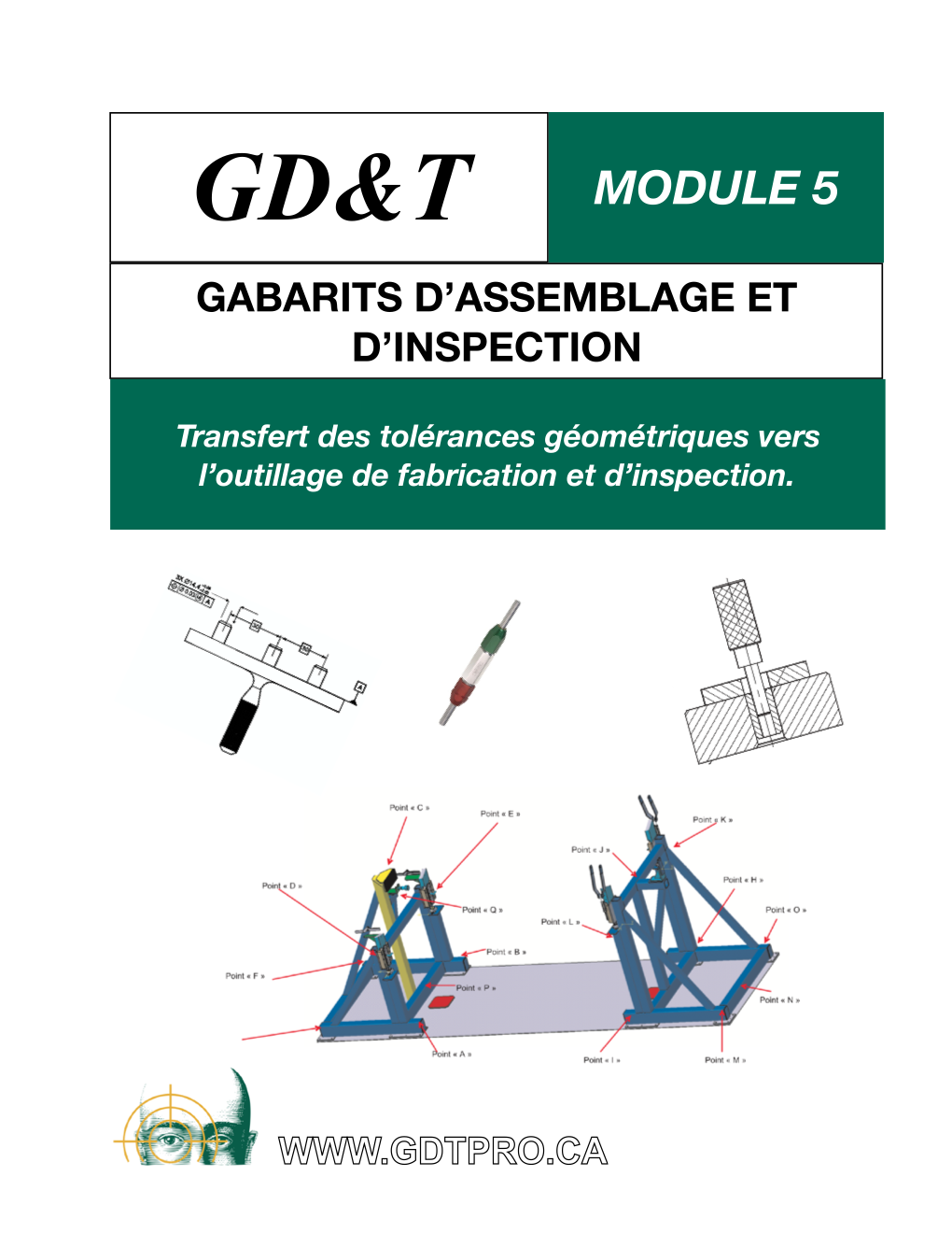
Les gabarits sont le pilier sur lequel s’appuie la fabrication en série de produits interchangeables. Ils permettent, à un coût unitaire très faible, de valider plusieurs caractéristiques des pièces de production. Il existe des règles et des normes strictes pour concevoir un calibre, qu’il soit du type Go-Nogo, calibre de localisation, ou n’importe quel autre gabarit d’inspection ou de maintient de pièces pour assemblage. La méthodologie proposée au Module 5 vise à donner aux participants une base solide leur permettant de concevoir des calibres conformes aux normes ISO, AGDC et ASME Y14.43. Que ce soit pour l’inspection 3D de grandes structures aérospatiales, ou pour le contrôle dimensionnel de petites pièces complexes, les techniques enseignées au Module 5 vous seront très utiles pour effectuer le contrôle des pièces en cours de production, et minimiser le besoin de faire des inspections finales au service d’inspection.
OBJECTIFS:
L’objectif principal du cours est d’introduire les participant(s)e aux grandes lignes de la conception des calibres d’inspection les plus fréquemment employés dans l’industrie (calibres dimensionnels, calibres de position et calibres de profil), et à la conception de gabarits de maintient des pièces pour l’assemblage respectant les tolérances géométriques et dimensionnelles du dessin de définition.
CONTENU:
> Principe de Taylor (ISO R1928, ASME Y14.5M-1994)
> Calibres à deux limites (tampon, mâchoires …)
> Calibres de localisation (simple, multiple et complexe)
> Calibres des profils (2D et 3D)
> Gabarits d’assemblage de grandes pièces
> Utilisation des techniques lancées de vision dans les gabarits
> Exercices synthèses
TRAINING DURATION: 2 days (16 h).
PREREQUISITE: Module 1, or a very good knowledge of GD&T as per ASME Y14.5.
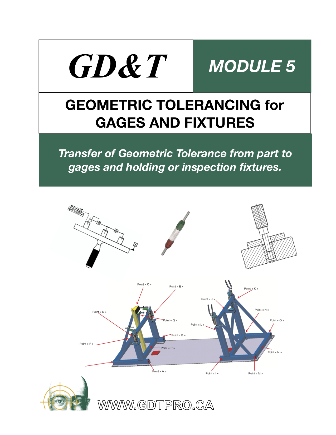
Gages and fixtures are the backbone of repeatable manufacturing since the 20th century. With gages and fixtures, parts can be inspected quickly, at a low cost, with a very high level of confidence.
Where holding fixtures are required by the process (ex.: welding of complex structures, assembly of aircraft components), it is desired that these fixtures be referenced to the 3D model of the parts, and provide ways for the production team to validate their products in reference to the fixture, without the use of a 3D measurement, saving time and money.
In module 5, participants will learn how to transfer geometric and dimensional tolerances from the engineering drawing to the manufacturing tooling.
CONTENT:
- Review of relevant GD&T concepts like Datum Reference System, surface control with the geometric tolerance of Profile, dimensional elements control with the geometric tolerance of position.
- Limit gages for linear size (Go-NoGO) according to ISO1931-1 (2015).
- The concept of virtual zone applied to inspection fixtures.
- Dimensioning and tolerancing principles for gages and fixtures (ASME-Y14.43-2011).
- Complex gages for position tolerance.
- Gage for profile tolerance.
- The process of qualification of large holding fixtures to the 3D model origin system.
[:]

